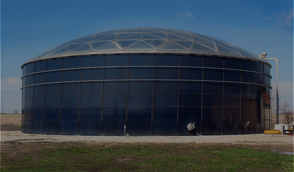

GLS Water TANKS
Common working procedures for “Glass-Fused-To-Steel”
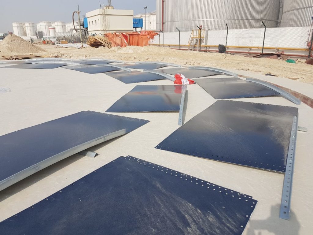
Work Requirement:
- The centre point and a reference point should be marked clearly before the start of the installation.
- The surface of the foundation rebate should be levelled, with a tolerance of +/- 5mm.
Setting foundation angle in rebate:
- The rebate is to be checked for level and roundness prior to commencing work, to identify & mark before setting foundation angle.
- The 0 degree position is located and using the drawing provided mark out the position of the first
angle. Drawing for anchor bolt location & fixing details. Drilling to be done perpendicularly to the concrete surface. - Fit the foundation angle and splice plates forming a perfect circle.
- Using the expansion anchor bolts, fix the angle down and secure it into position. Use 3 anchors
per angle. Torque test to be as per required torque specification. This angle is to be used as the sheet support guide for fixing all plates.
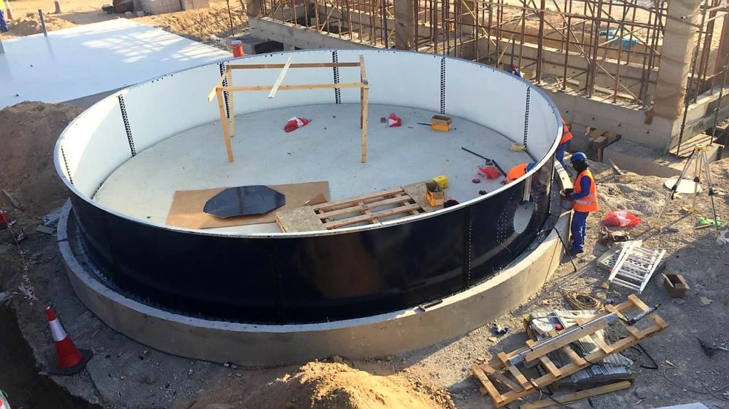
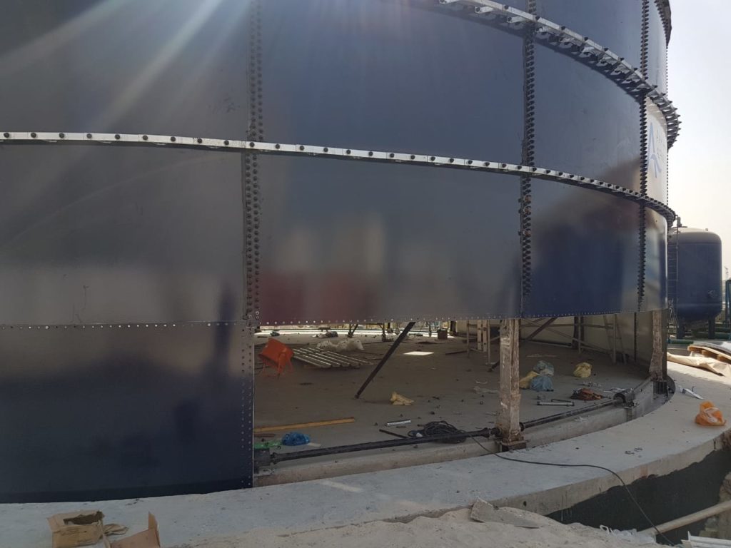
Installation of the bottom/foundation ring:
- For ease of wall panel installation, a rough terrain fork lift truck or crane will be used to move each wall panel into the required position.
- The first wall panel will be placed into the rebate, bolted to the bottom angle. Sealant is then applied over the connecting bolt holes on the right hand side of thepanel.
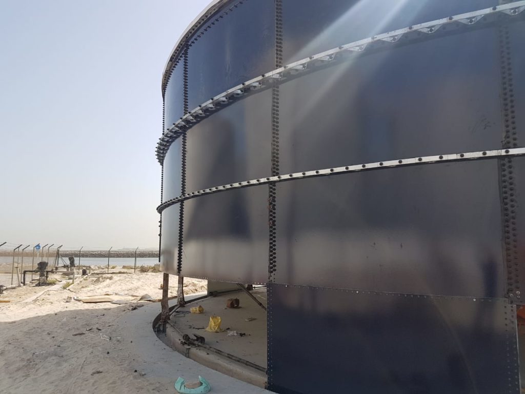
- Using an alignment bar, the next wall panel is aligned to the previous panel before the bolts
are placed through the sheets and washers and nuts applied. The bolts will then be tightened
using electric air impact wrenches. After tightening is complete the squeezed out sealant is
filleted off and plastic cover caps are applied over the nuts. - Repeat procedure (e) till the whole ring is installed.
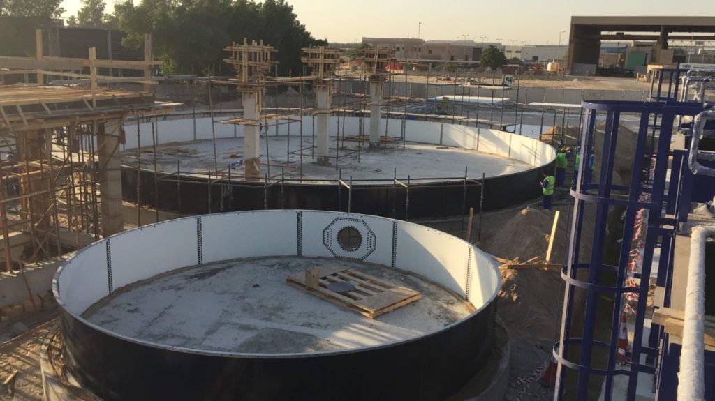
- Top angles can be fitted during the ring construction to aid the circularity of the tank.
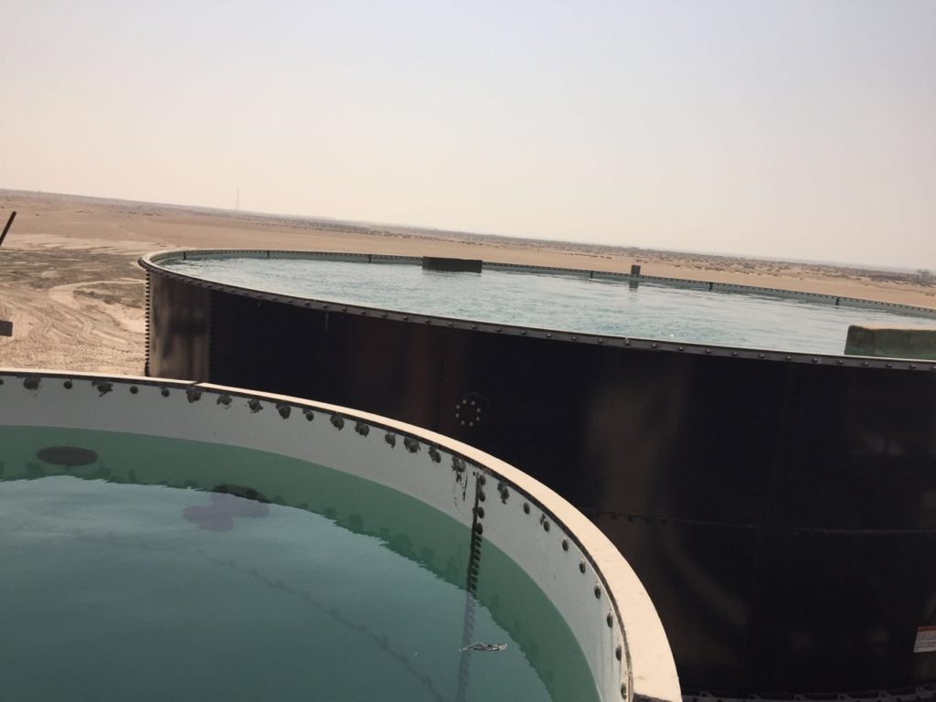
- After each ring is completed, cleaning and visual checking (internally and externally) will be
done to the tank wall to ensure no physical damage/scratches etc.
Seal strip/ ‘J’ tape placement & concreting sealing:
The concreting of the tank into the rebate can be undertaken at any time after the installation of the tank bottom ring. The seal strips are to be applied just prior to placement of the concrete. The seal strips should not be applied during precipitation, or in temperature below 20 degree F
- Rebar is positioned on the Inner & outer part of the tank for added strength before grout commence.
- Before application of seal strip, make sure to clean the area so that the strips maintained full contact when applied.
- When applying the grey seal strips to foundation sheets, vertically lap each seal strip over the previously installed seal strips.
- The bentonite black seal strip should then be installed directly below and tight against the grey seal strips. Full contact should be maintained between the black seal strips and surface.
- The end of the black seal strips should be butted, not lapped in the manner described for the grey seal strip.
- Grey seal strip is applied to the face of the rebate.
- Concrete is then delivered and using a concrete pump placed into the rebate.
- The concrete is vibrated and levelled into the correct position. Great care is to be taken to ensure that the seal strips are not disturbed during the concrete pour.
- The tank sheets are cleaned of all ‘splats’ of concrete.
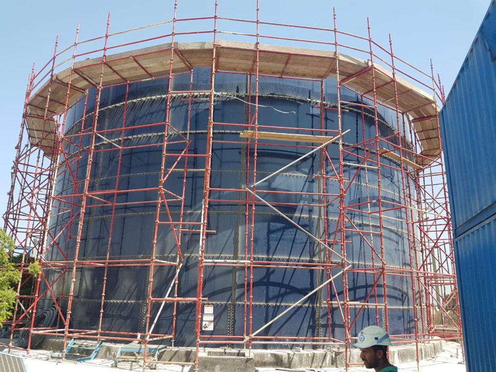
Installation of 2nd wall panels:
- The tanks are to be constructed using the scaffold build method. Set up a scaffold on the inside and outside of the tank at the height the ring that you are working on.
- Select the starting point for the first panel of the next ring and apply sealant to the horizontal row of bolt holes at the bottom of previous ring supported on the jacks
- Lift the first panel onto the bottom angle positioned in the rebate (using a crane or Rough terrain felt if necessary) and using alignment bars the panel is aligned to the panel above and the bolts are placed through the sheets and washers and nuts applied. The bolts will then be tightened using electric or air impact wrenches. After tightening is complete the squeezed out sealant is filleted off and plastic cover caps are applied over the nuts and will torque test as per required torque value.
- Apply sealant to the right hand side holes of the last panel placed and horizontal row of bolt holes at the bottom of the next panel. Lift the next panel for the ring onto the bottom angle and using alignment bars the panel is aligned to the panel above and on left and the bolts are placed through the sheets and washers and nuts applied. The bolts will then be tightened using electric or air impact wrenches. After tightening is complete the squeezed out sealant is filleted off and plastic cover caps are applied over the nuts.
- Repeat the previous instruction until all panels of the rings are installed.
- Use the splice angle temporary attached to the top of the sheet to ensure circularity.
- Repeat the previous procedures (a, b, c, d, e & f) for each additional ring.
- When the final ring is installed the top angle is permanently fitted to the top edge of the sheet & Splice angles are fitted to ensure circularity.
Installation of Site-Cut connections (If any, site Requirement):
Where possible connections are to be installed at ground level as work progresses this minimizes working at height and makes for easier fitting.
- Determine the position of the nozzle by referring to the Tank Specific GA drawing. Once site cut nozzles are cut they cannot be changed.
- To mark the vertical plumb line and horizontal height of the nozzle of the tank sidewall.
- Offer the appropriate nozzle into position and mark all the flange holes onto the tank sidewall.
- Drill all the tank flange holes starting with a pilot drill, working up to a 14mm drill bit for the actual tank bolt hole.
- Mark the position of the flange hole onto the tank sheet.
- Add 10mm to the diameter of the tank flange hole and using a combination of drill bits and jigsaw cut the hole. NOTE you have drilled the hole bigger than the connection, this allows the edge of the tank plate to be covered with mastic when fitting ofthe nozzles.
- As soon as the sheet is cut, the edges of the holes are to be protected & clean and apply mastic fillet over the cut surface.
Fitting of connections/Man ways:
- Apply mastic to the flange area, both internally and externally.
- Attach the backing ring to the inside of the tank using a silo bolt. The top hole is used that will allow the backing plate to hang.
- The connection is then offered to the outside of the tank and using the nut fitted to the tank.
- The procedure is followed for all bolts on the flange.
- The nuts are firstly tightened by spanner, ensuring that they are tightened in the correct pattern as identified in the Assembly Guide.
- The nuts are then ‘torqued’ to the correct level as identified in the Torque Chart.
- The external nozzle and internal backing plates are pointed to give an aesthetically pleasing finish.
Ladder Cage Installation:
- Determine & assemble the tank components for the specific tank.
- Locate the top & bottom hoops and attach the cage hoop for the same.
- . On the assembled cage hoop, install the provided vertical bar to form a cage like ladder.
- For ease of installation, a mobile crane will be used to install the ladder cage.